MOSFET Reference
This note summarizes the key characteristics of MOSFET and some of its typical use cases. Some of the figures and tables are taken from tutorials listed in the Reference section.
MOSFET Types
MOSFET is a type of device where the current flows between its drain and source terminals (\(I_D\)) can be controlled by the voltage between its gate and source terminals (\(V_{GS}\)). There are 4 types of MOSFET: N-channel, P-channel of enhanced type or depletion type for each. Their symbols are given below [1]:

Enhanced-type N-channel MOSFET (NMOS) is the most commonly used type. Enhanced-type P-channel MOSFET (PMOS) may also be used in certain cases. Depletion type MOSFETs are rarely used in practice.
MOSFET is often used a switch and it operates between its cut-off region and saturation region. The state of its connectivity between drain and source is given in the following table [1].
| MOSFET type | \(V_{GS}\) = +ve | \(V_{GS}\) = 0 | \(V_{GS}\) = -ve |
|---|---|---|---|
| N-Channel Enhancement | ON | OFF | OFF |
| P-Channel Enhancement | OFF | OFF | ON |
| N-Channel Depletion | ON | ON | OFF |
| P-Channel Depletion | OFF | ON | ON |
Use N-channel enhanced type MOSFET as an example, you can consider it as a voltage-controlled resistor. When \(V_{GS}\) is smaller than \(ve\), the resistence is very large and when it's bigger than \(ve\), the resistence becomes very small (\(R_{dson}\)).
MOSFET as a Switch
The following are two typical use cases of NMOS and PMOS as a switch. [3]
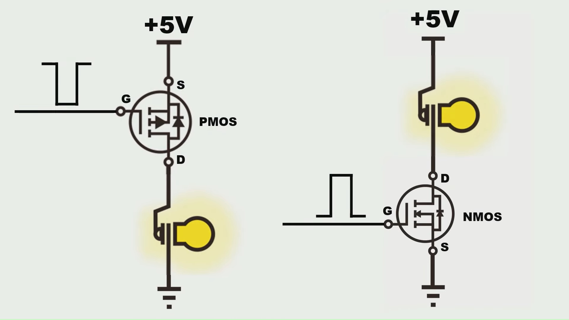
Because NMOS is turned on when \(V_{GS}\) is high, it's normally placed at the lower side connecting to the ground so that it doesn't require a very high voltage to turn on. For similar reasons, PMOS is usually placed at the top side conntecting to the power positive so that it's easy to turn it on by pulling the voltage at gate low.
Another difference to note is that the current flows from source to drain in PMOS, which is opposite from the current in NMOS.
Practical Design
A circuit that uses NMOS to trigger a relay to power a motor.

- R1 and D2 are used to indicate ON/OFF state of the relay
- D1 is a flyback diode
- R4 is a pull-down resistor
- R3 is used to limite gate current, control switch on/off speed of the NMOS
- A zener diode can be connected between gate and source to protect the MOSFET to be damaged by high voltage (in parallel to R4)
- A diode may be added in parallel to R3 (pointing to control input) to reduce the turn-off time
Reference
- [1] https://www.electronics-tutorials.ws/transistor/tran_6.html
- [2] https://www.electronics-tutorials.ws/transistor/tran_7.html
- [3] https://www.youtube.com/watch?v=Uk1CPNROjNk